


MC3 astronomical telescope controller
The MC3 makes the use of the astronomical telescope more convenient and comfortable. It can be configured to wide selection of astronomical mounts and compatible with many planetarium programs.
The MC3 is a basic telescope controller, provides telescope control without encoders. If you would like to use your telescope with encoders check the MC5 on the separate page.
Table of content
Introduction
This is a flexible telescope mount controller. Designed for astronomical telescope mounts, but it is more universal: Can be used to control panoramic photo heads and custom made timelapse devices also.
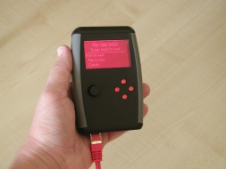
You can find more information about the Ursa Minor Hand Control on a separate page.
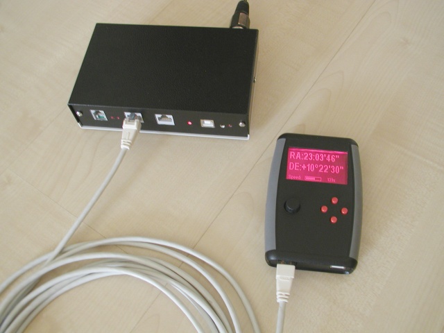
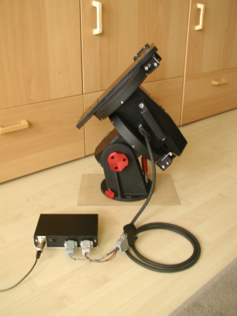
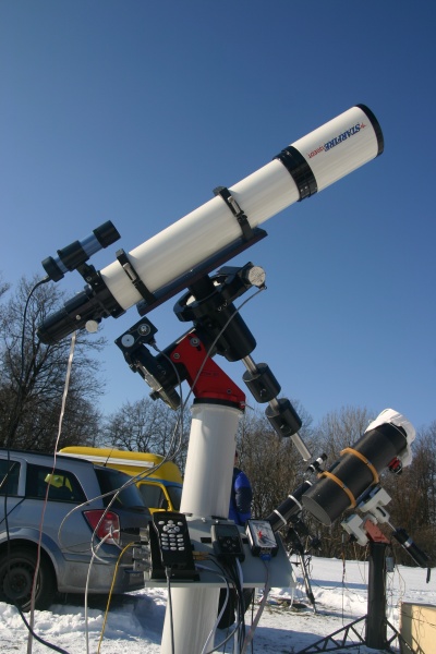
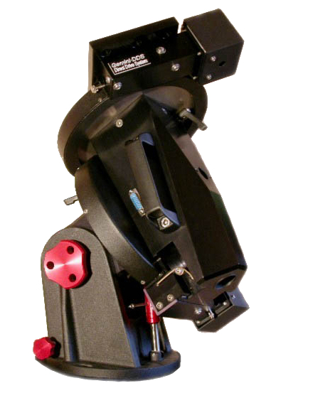
Illustrations: Left:The Motor Controller connected to Gemini G42 mount. Right: Using MC3 with Fornax 50 mount.
Features
- Freely configurable to most of the telescope mounts
- Easy to use Hand Control Unit with graphic display
- Internal astronomical database with 50000 objects
- Ascom compatible: Compatible with most of the planetarium programs with dedicated Ascom driver.
- Battery backed real time clock in the Handset. Does not forget the time and place!
This device is suitable for medium to large telescope mounts. It provides control, goto (automatic positioning to the selected celestial object), auto-guiding (Tracking the selected object) functions. The equipment drives two-phase stepping motors.
Supported mounts
The MC3 can fit to multiple telescope mounts. It depends on two things: the type of motors used and the gear ratio. The MC3 can drive two phase bipolar stepper motors and can be configured to wide range of gear ratios.
The operation is guaranteed (tested) with these mounts:
- Fornax 51, 100, 150 mounts
- These are popular Hungarian-made mounts. Robust, rugged, heavy duty, accurate equipment. The MC3 is compatible with all family members of the Fornax 51, 100, 150 family. You can buy the MC3 control together with the mount. In such case you can ask us to make all the complete configuration, set-up work and your system will be ready to use immediately.
- Stabi mounts
- These precise mounts are also Hungarian-made. They are a bit smaller and more transportable than the Fornax series. You can buy the MC3 control together with the mount. In such case the complete configuration, set-up work is carried out by us. Your new mount will be immediately ready to use.
- Gemini G42 and F53
- Gemini G42 and F53 series mounts has built in bipolar stepper motors. These mounts can be controlled with MC3. The F53 mount has built in encoders. The mount can be controlled with MC3 without the encoder feedback.
- Skywatcher EQ6 and EQ8
- These Skywatcher mounts has a built-in electronics and fast stepper motors. After removing the original electronics and provide direct connections to the motors, the mount will be ready to work with MC3. It has more advantages: The Ursa Minor Hand control has many improvement: (battery backed real time clock, easy operation with one hand, easy selection of reference star by choosing it on a displayed chart.) Thanks to the advanced electronics of MC3, the motors will run more smooth and they will be capable for higher speed.
- Other or custom mounts
- The gear ratios (independently for the two axes) and motor parameters are freely configurable in the MC3. It makes possible to adapt it to a wide range of telescope mounts. You need to know the gear ratios and motor step/revolution parameters and make a custom motor cable depending on the actual type of motors.
Use with hand-held controller or computer
For using the MC3 you will need a hand control or a computer (with appropriate software). The following list summarizes the options:
- Ursa Minor hand control
- Easy to use hand control, developed directly for the MC3. For more information, please go to this page.
- Connection with Ursa Minor Pro program
- The Ursa Minor Pro program directly supports the MC3 controller, ASCOM driver is not required. Using fewer software components and additional drivers gives more convenient way to use. The Ursa Minor Pro gives some extra functions: DSLR camera control, sequential shooting, sending autoguider and goto signals in one cable.
- Using MC3 with other programs
-
The MC3 controller is compatible with most of the astronomical softwares via Ascom driver. you have two options:
- Dedicated Ursa Minor Ascom driver: This is the recommended way.
- Using LX200 protocol: The MC3 works with the "Generic Meade LX200 Ascom Driver".
Technical Specifications
Features and Electrical parameters
| DC supply voltage | 12V - 30V (24-30V stabilized power supply recommended) |
| Max. supply current | 2,5A |
| Max. motor pulse current | 1,8A |
| Hand Control | Ursa Minor Hand Control Unit |
| Computer connection | USB port |
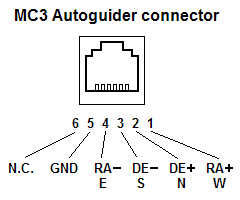
| Autoguider port | RJ/11 (6 pin telephone socket) ST4 compatible |
| DSLR trigger output | 2.5mm stereo jack, opto-isolated |
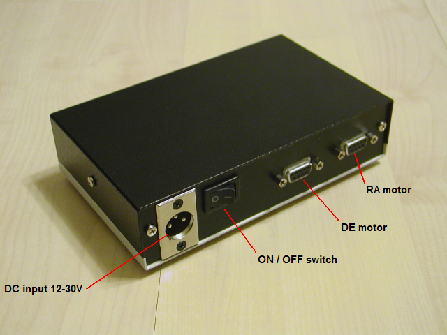
Front connections
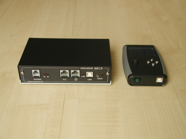
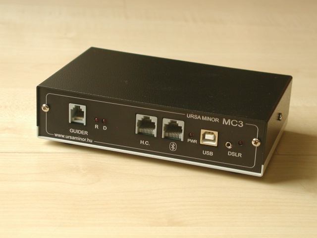
MC3 front connections from left to right: Autoguider, Ursa Minor hand control, Utility connector (For Bluetooth interface or other accessories), USB port, DSLR camera remote output.
Pinout of the autoguider connector:
Rear connections
Here you can find the power supply connector, the on/off switch and connectors for two motors:
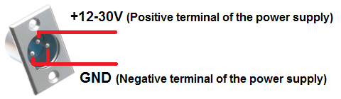
Pinout of the power supply connector:
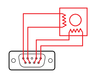
Wiring the motor connectors on the back side of the MC3. Each wire has two pins tied together providing more reliable connection.
Adapting the MC3 to a telescope mount
The device can be used with various kind of bipolar stepper motors. Some examples shown below:
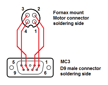
Fornax mounts have 4 pole circular motor connectors. The following image shows the construction of the necessary motor cable. One cable required per motor.
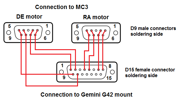
Gemini G42 mounts have one 15 pole D-Sub connector as motor connector. Both of the two Motors are wired to it inside of the mount. The following image shows the construction of the necessary motor cable to connect the G42 to the MC3.
MC3 can be used for wide range of mounts, even the custom ones without documentation. The most important requirement is, the mount should be equipped with two phase stepper motors.
Because we do not have the documentation of the motor pinout in such case, you should identify the wires by an ohmmeter. Two phase stepper motors contains two coils inside. These are insulated from each other and the metal body of the motor. These coils are equivalent and they represent similar ohmic resistance. It can be measured by the ohmmeter.
You should search the both end of the same coil by measure the resistance between the wires, trying all the possible variations. If the motor has 4 wires. It is a two ends of the two wires. If there are 6 wires, the two extra wires are the center taps of the coils. These should be not used with MC3 system. Insulate the center taps from any of the other wires.
After you identified the 4 necessary wires (ends of the two coil) you should make a custom cable with the following pinout on the MC3 side:
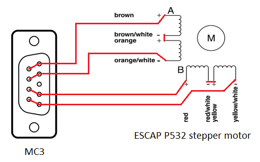
For 8 wire stepper motors you have in general two options: Serial and parallel connection. In most of the cases the MC3 works better with serial connection as shown in the picture below. In the example we use the Escap P532 motor.
Important thing: The east / west position of the mount
There is an important issue when you are using a german equatorial mount: The sky cannot be scanned with the telescope from the eastern horizon to the western horizon. Somewhere at the middle the telescope may collide to the mount. In such case you should do a Meridian-flip: Move the tube to the opposite side of the mount.
Please imagine you have a german equatorial mount. The telescope is pointed to the South towards a star near the equator. In such case your telescope may in one of the two possible positions:
- Eastern position:
- The telescope is at the eastern side of the mount. The counterweight shaft is pointing to the West.
- Western position:
- The telesope is at the western side of the mount. The counterweight shaft is pointing to the East.
It is essential to know which position you are using. Not only you, the Motor driver unit also must know this. It is essential because the rotation direction of the declination motor is the opposite in the two cases.
The motor control unit does not know it as its own. You should tell it during the initial setup.
By using the hand control
Trere are some predefined default positions. You should move the telescope to one of these and choose the appropriate item in the Hand Control's Init scope menu.
By using the MCConfig program
Using the MCConfig program, you should set up the telescope to the default eastern or default western position, and press the "east" or "west" button in the "Pier side" panel in the program's window.
By using the Ursa Minnor Pro program
Move the telescope to one of the predefined default positions and choose the appropriate option on the program's Init Scope menu.
These steps are necessary only at once, at the initial setup. They are not necessary when you park the scope properly at the end of the previous use.
What to do before use
Assembly
Connect the cables only when the power is off!
- Connect the motor-cables of the mount to the two-D9 connectors at the back of the MC3 controller.
- Connect the power supply unit to the MC3-controller (PSU is already plugged in into the mains socket), but do not yet turn on the device.
- Connect either the Ursa Minor hand control unit or a computer (but only one at a time, never both at the same time as that will confuse the electronics as the MC3 would want to process information from two competing sources).
When you use it first time for the initial settings you would need to connect it to a PC or laptop.
Connection to the computer via a USB port
- Download and install the FTDI USB serial driver.
- Connect the MC3 to the computer via a USB cable if you have not already done so.
- Turn on the MC3.
- Find out what is the COM port number of the device.
- Start the program ”mcconfig” for the initial setup.
Initial setup using computer (With the MCConfig program)
The MC3 device normally comes pre-configured for the Fornax mounts. (Exception: if you buy with a different mount and also ask us to pre-configure it.) You may need to adjust settings for your equipment even if you already have a Fornax mount.
A program called “MCConfig” serves to setup the mount.
The current version of the program is 2.6. You can download it from the downloads page
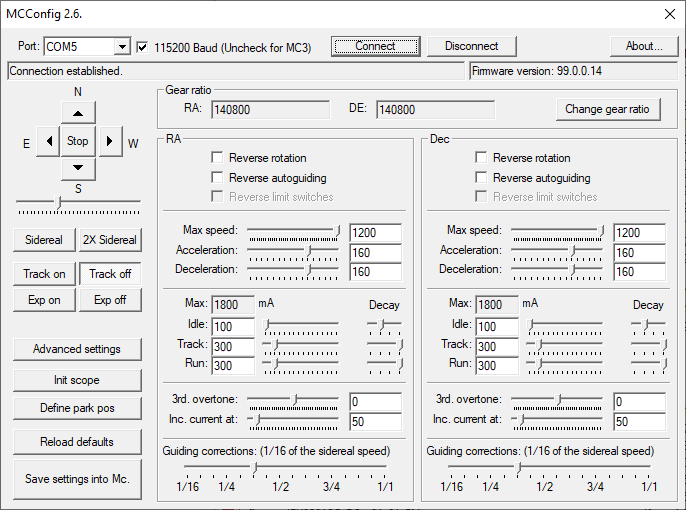
The program requires no installation. Just unzip the zip file. The program's user interface looks like this:
Steps of initial configuration
Before doing anything, consider the pier side of the mount. We recommend the following initial position:
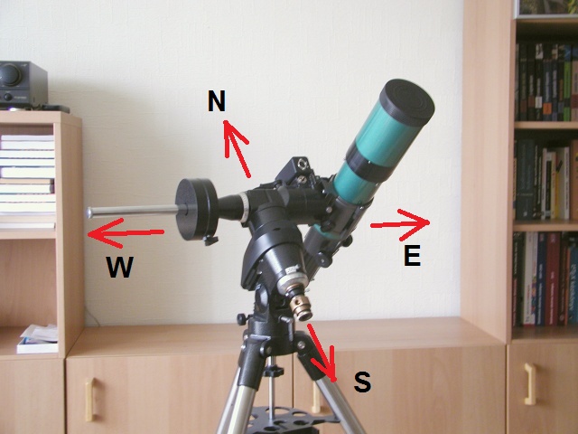
The telescope is at the eastern side of the mount and looks to the Equator. The counterweight shaft is horizontal and points to the West.
The MCConfig program assumes this initial position at the beginning.
- Connect the MC3-controller to your computer, if you have not already done so. (via a USB cable)
- Turn on the MC3-controller and start the program “mcconfig”.
- Select the COM port number (that you found out after the installation of the FTDI driver) from the drop-down list in the upper left corner of the window. The COM number can be discovered by this way.
- Select the Baud rate (this is the speed of communication). MC3 needs 9600 Baud. MC5 needs 115200 Baud.
- Press the "Connect" button and wait until the connection is established. Below the Connect button the following message would be displayed "Connected".
- Once connected, the program reads the settings from the MC3 and accordingly displays them in the window.
- At first, set up your geographic position. The geographic position is stored inside the motor controller. Press the
"Advanced settings" button, and enter the coordinate values into the fields.
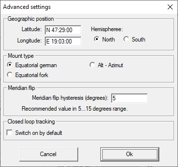
- Please also select the correct hemisphere! (Entering the proper geographic latitude is not enough. The hemisphere selection is also important.)
- Please check and set the type of the mount (german equatorial or fork mount). Do not choose the alt-azimuth option, as the controller does not support this kind of mount yet. This option is reserved for future developments.
- The checkbox at the "Closed loop tracking" section should be unchecked. this option is not available for MC3.
- Close the advanced settings window by pressing the "Ok" and you should see the "Settings done." message in the status field.
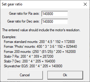
- Check the gear ratio and modify it if required. The values displayed on the screen are the gear ratio multiplied
with motor steps.
Example: A Standard Fornax 51 mount has a 192 teeth worm gear, a belt drive with 4.5 ratio and a 200 step per revolution motor. The entered value should be: 192 x 4.5 x 200 = 172800.If your mount's total ratio is different than the displayed value, press the "Set gear ratio" button and give the correct values in the popup window.Important: After changing the gear ratio, all settings should be reviewed, and the park position must be set again. (Changing gear ratio resets the park position.)
- With the help of the four direction buttons at the top left corner of the window you can now try to move the motors. When you click the arrow button the mount would start to move in that direction. To stop it you would have to click on the STOP button that is placed in between the four direction buttons. Until you click on the STOP button, the motors will NOT stop moving!
- The speed of the movement can be adjusted with the slider just below the direction buttons. Please note, the slider has effect only on manual movements started by these direction buttons.
- Make sure that the RA axis of your mount is connected to the right port and that it tracks in the direction of East to West. First, stop the motor (if you have not done yet), then press the button “Track On”. Tracking starts.
- Check out if it tracks in the right direction and whether the object remains in the telescope's field of view.
- If the motor rotates in the opposite direction then thick the “Reverse Rotation” checkbox under the RA panel.
- Now we can proceed with the declination motor. You should pay an extra attention because the rotation of the
declination motor is dependeing on the pier side. For the initial setting, the telescope's
orientation should be the similar as the eastern position displayed above. Ensure, thet the orientation of the mount is
similar! The telescope should be at the eastern side of the mount and looks to the Equator. The counterweight shaft
should be horizontal and points to the West. If not so, move the telescope into this orientation. Press the "Init
scope" button!
Choose the "Default east - Equator" option, and press "Set this position" button.
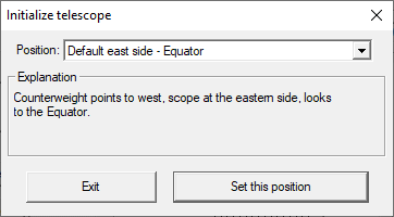
- You should see the "Telescope synchronized to the given position." message in the status field.
- Now try to move the declination motor: Press the up button, and the telescope should move to north. If it is not so, please reverse it by checking the check box at the upper part of the declination panel on the screen.
- Now check the maximum speed of the motors. It can be adjusted independently for both axis. At first, adjust the
slider just below the direction buttons to its rightmost position.
- Give a value for max. speed for the RA motor at the RA panel with the uppermost slider.
- Now try the movement of the motor.
- If the speed is too fast, the motor will stop and give a noise. This means it ran out of synchron.
- In such case you should stop it completelly, give a bit smaller max speed and test it again.
- Adjust the max speed of the declination motor similarly.
- Now set up the park position. As you processed the steps of the setup above, the telescope is at the eastern side
of the pier. If the desired park position is also in the eastern side the process is simple. If the park position is at
the opposite side, a few more steps required.
If the park position is at the same side of the pier
- Move the telescope to the park position
- Press the "Define park pos" button!
If the park position is at the opposite side of the pier
- Move the scope to the opposite side of the pier, to the desired park position (by buttons, or by opened clutch)
- As the scope is at the opposite side, the declination motor's rotation is not correct. Do not reverse it now!
- Press the "Init scope" button and choose one default position which is the closest to your desired park position.
- Press the "Define park pos" button!
- If you have completed all the above necessary steps/settings, there is one important step remains: You have to store the settings in the memory of MC3. To do this, press the “Save settings into Mc.” button. When you turn the MC3 on next time, it’ll work with the new settings.
- If you have finished with setting it up, disconnect it by clicking on the “Disconnect” button and then turn off the MC3.
Recommended MC3 configuration parameters for some popular mounts
| Fornax 50 series (Fornax 50, Fornax 51, Fornax 52) | Fornax 100 series | Fornax 150 series | Fornax52 "Photo" series (Discontinued models) | Stabi 1.0 | |
|---|---|---|---|---|---|
| Gear ratio | 172800 | 172800 | 172800 | 829440 | 179500 |
| Motor steps | 200 | 200 | 200 | 400 | 200 |
| Idle current | 600 mA (*) | 600 mA (*) | 600 mA (*) | 600 mA (*) | 400 mA (*) |
| Tracking current | 1400 mA | 1400 mA | 1400 mA | 1600 mA | 1000 mA |
| Running current | 1400 mA | 1400 mA | 1400 mA | 1600 mA | 1200 mA |
| Max. speed (30V) | 400 x | 400 x | 400 x | 200 x | 540 x |
| Max. speed (24V) | 360 x | 360 x | 320 x | 160 x | 540 x |
(*): Remark: For optimal guiding performance, the idle current for DE axis should be set to the same value as the tracking current.
Remark 2.: The Fornax "Photo" mounts have very high gear ratio. (4.8 times larger than standard Fornax mounts) This makes difficult to provide high speed movements. The step frequency needed to 300 x speed may produce 1440 x speed on a standard Fornax mount. This high speed is not recommended in most of the cases.
Initialization on the Southern Hemisphere
The initialization procedure is similar than on the Northern Hemisphere. The recommended default position is shown in the following image:
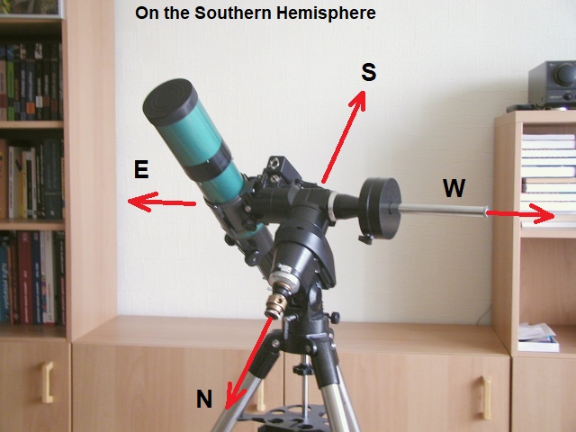
Initialization on the Southern Hemisphere. The telescope is at the eastern side of the mount and looks to the Equator. The counterweight shaft is horizontal and points to the West.
Initial configuration with Ursa Minor Hand Controller
This process is described on separate page.
Upgrade the internal firmware of the MC3
You can upload new firmware into your existing MC3. New firmwares are released when new development or bug fixes were made. Use the MC3_bootloader program for that purpose:
You also need a firmware file. These can be downloaded from there.
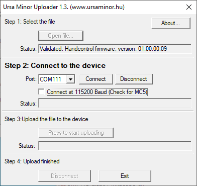
The upgrade procedure consists of four steps, as the user interface of the program also separated into four areas. Each area in the window has a title. The title of the active area is displayed with bold fonts.
The steps of the upgrade process:
- Connect the MC3 to the computer and switch it on.
- Do the step one in the Uploader program: Open the firmware file. After the file opened, the program validates it. When the file is correct, the program let you step tot the second phase.
- Connect to the MC3. Choose the COM port number, and press the Connect button. The program will check the version of the MC3 hardware and checks the compatibility with the new firmware file. If the file is compatible with the MC3, the program let you step to the third phase.
- In this phase you can start the uploading process. This may take a few minutes. The progress is displayed in the status field. (Number of total sectors and number of uploaded sectors.)
- When the uploading is done, you should close the program and switch off the MC3.
Important: After uploading a new firmware, the MC3 should be restarted before use it.
Important: Upgrading the firmware will reset the MC3 parameters. You should configure it with the MCConfig again.
Upload the firmware in Safe Mode
When an error occurs during the firmware upload, the MC3 may not start properly on the next startup. In such case the uploading a new firmware also may not be possible.
When this situation happens, you should start the MC3 in safe mode:
- Open the MC3: Remove the cover of the device.
- Locate the jumper. There is only one jumper inside the MC3.
- The jumper is in the open state normally. Put it into the closed state.
- Start the MC3. The two autoguider LEDs will blink alternatively. It indicates, that he MC3 is in programming mode.
- Upload the firmware as normally.
- When the upload finished, switch off the MC3 and put the jumper back into open state.
Important: Open the MC3 only when the power is off! Handle the jumper only when the power is off!
Using with Ursa Minor hand control
The Ursa Minor hand controller is designed directly for MC3. You can read about it on separate page.
Using MC3 with the Ursa Minor Pro program
The Ursa Minor Pro program supports all functions of the MC3 / MC5 (OC5) controllers. You can read about this on the following page.
Controlling the MC3 with computer, via Ascom driver
A dedicated ascom driver is developed for the MC3 and MC5 (OC5) telescope controllers.
Previous MC3 models were using Meade LX200 protocol, but for the improved functions (For example: properly handling pier side) we decided to develop and use our own Ascom driver.
You can read more detailed information about the ascom driver on the following page.
Most of the planetarium programs are ascom compatible. The steps of the connection is the following:
- Connect the Hand Control to the MC3!
- Connect the MC3 to a computer with an USB cable. (The USB socket of the and Control should be remain unconnected)
- Switch on the MC3! The System will initialize itself and initializes the telescope position as it wake from park.
- Check the geographic coordinates and the current time in the Hand Control's menu.
- Do a refernce star adjustment with the hand control. (It may be done later from the planetarium program also.)
- Start the planetarium program on the PC.
- In the planetarium program, navigate to its telescope control menu and choose the Ursa Minor Telescope Ascom Driver.
- The system is ready to use with the planetarium program.
When you finished, the switch off sequence should be the following if the planetarium program supports parking:
- Send the telescope to the park position with the planetarium program.
- Disconnect the MC3 from the planetarium program.
- Switch off the MC3.
- Unplug the USB cable.
When the planetarium program does not support parking, the switch off sequence should be the following:
- Disconnect the MC3 from the planetarium program.
- Send the telescope to the park position by the Hand Controller.
- Switch off the MC3.
- Unplug the USB cable.
Auto Guiding (Automatic Tracking) with a computer
In this example you can read about how the MC3 works together with an autoguider program running on your computer. There are many different ways of guiding with a computer, but in this example we will be using the PHD Guiding program.
In this example, we do not use a planetarium program. The GOTO positioning will be carried out by using a hand controller unit. The guiding is done by a help of a webcam and the autoguider program.
The steps are as follows:
- Connect the hand controller to the MC3.
- Connect the MC3 to your PC with a USB cable. The MC3 autoguider port is left blank.
- Turn on the MC3.
- Find out what COM port number was allocated to the MC3.
- Start the autoguider program.
- In the autoguider program, navigate to its telescope control menu and connect to the MC3. Please choose the "Ursa Minor Ascom Driver".
- The system is ready to use.